
Introduction
The main objective of this publication is to provide a checklist of what is needed to properly prepare a center pivot or lateral irrigation system for the production season. All of the topics covered apply to both pivot and lateral irrigation systems, but for brevity and because of their popularity, only center pivots will be referenced. By using this publication as a guideline for preventative maintenance, you should be able to lessen the risk of breakdowns during the growing season. Preventative maintenance will save you time, money, and yield during the production season.
Center pivot irrigation systems are used heavily during the production season with some operated continuously throughout the season. But when we are finished with it for the season, it gets stored until we need it again, and then we expect it to operate perfectly with very little maintenance. For example, freezing temperatures during winter can cause damage to center pivot systems that are not properly winterized. Extreme cold weather causes many issues in water pipes throughout the system; therefore, it is very important to check pivots for freeze damage several weeks before you need the system for crop irrigation. Systems need to be in top shape when it’s time for that first application of irrigation water.
Review the following checklists for an overview of things that should be taken care of before you start up your irrigation system.
START-UP CHECKLIST
Power Unit
Service the engines, including changing the oil and oil filter (typically recommended at a minimum every 6 months or 100 operating hours), fuel filter, air filters, and spark plugs (if applicable). Check the fuel lines for leaks and deterioration, the wires for pest damage, and the bolts securing the drive shaft to the pump. Grease the drive shafts and service points; fill the coolant system, ensure that the pump packing is in good condition, and remove any debris around the motor.
If the unit is sluggish or will not crank, have the battery checked to see if it can be charged or if it needs to be replaced. While diesel power units have more components than electrically driven pumps, the electrical motors driving the pumps need to be checked. Check the driveline, couplers, and the bolts that attach the drive to the motor.
Also check the electrical lines to the motor to ensure they have not been damaged. The power unit is one of the most important components of the irrigation system, so the best time for this type of preventative maintenance is several weeks ahead of operation.
Pumping System

Centrifugal
The pump should turn freely and gaskets should seal properly. Check for leaks, any premature signs of deterioration, wear, or seizing of components. Verify sufficient lubrication and that pump and piping is properly supported.
Turbine
Check the lubrication control system and service if necessary. Ensure that the discharge piping is firmly supported and securely bolted, maintaining the packing if applicable. If using a submersible motor and pump, it is critical that the static level and drawdown in the well is monitored. See the related publications section for recommended pumping time and drawdown testing.
Suction (Intake) Line for Surface Water
Verify that the intake line and screen are clear; ensure that the intake line is properly supported; and repair leaks as needed. If possible, pull the pipe out of the water and check on the condition of all suction components.
Piping / Drains
Close all manual drains; verify that control valves are working properly; inspect aboveground pipes, gaskets, seals, etc.; and replace drains in the booster pumps.
Electrical System
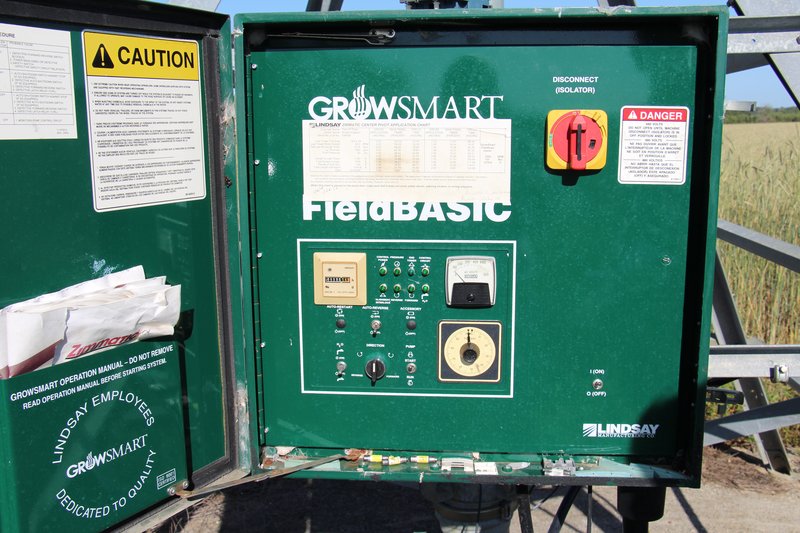
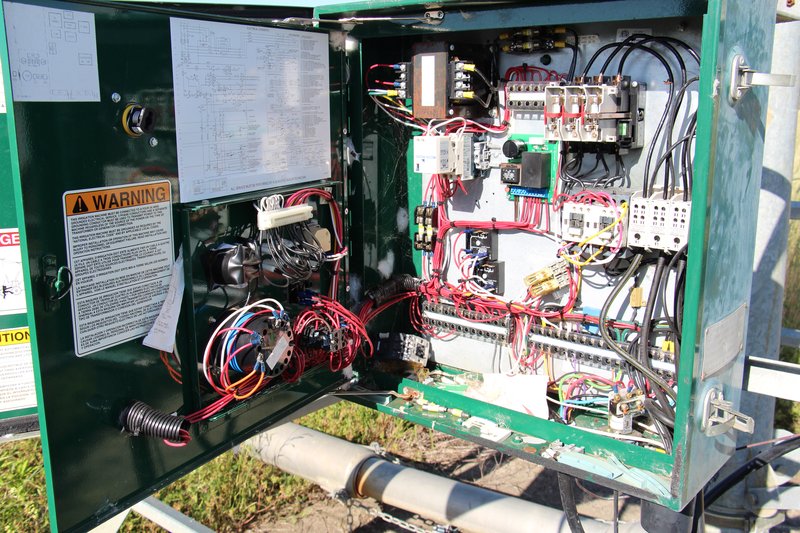
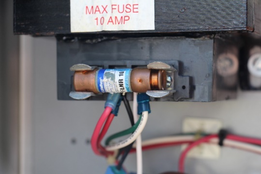
Use proper safety procedures when checking the electrical system. Pivots operate on 480 volts of three-phase power, which is deadly. Always touch the door of the panel box (Figure 1) with a noncontact volt meter or the back of your hand to ensure it is not charged with electricity. Verify power connection to pivot is operational and that the electric pump motor is in good working order. Inspect the pivot control panel for any debris, insulation damage, loose bolts, screws, or nuts, and frayed or burnt wires (Figure 2). Check the condition of fuses (Figures 3 and 4) and ensure that you have a few extra fuses available. Verify that the wiring/cabling on the pivot is sound. If you observe any problems, immediately shut off power to the system and repair the damage.
There may be other components to your center pivot system not included in this pre-operation checklist. If so, check those components according to manufacturer recommendations. Next, turn the system on and go through the operating checklist.
OPERATING CHECKLIST
Pressure
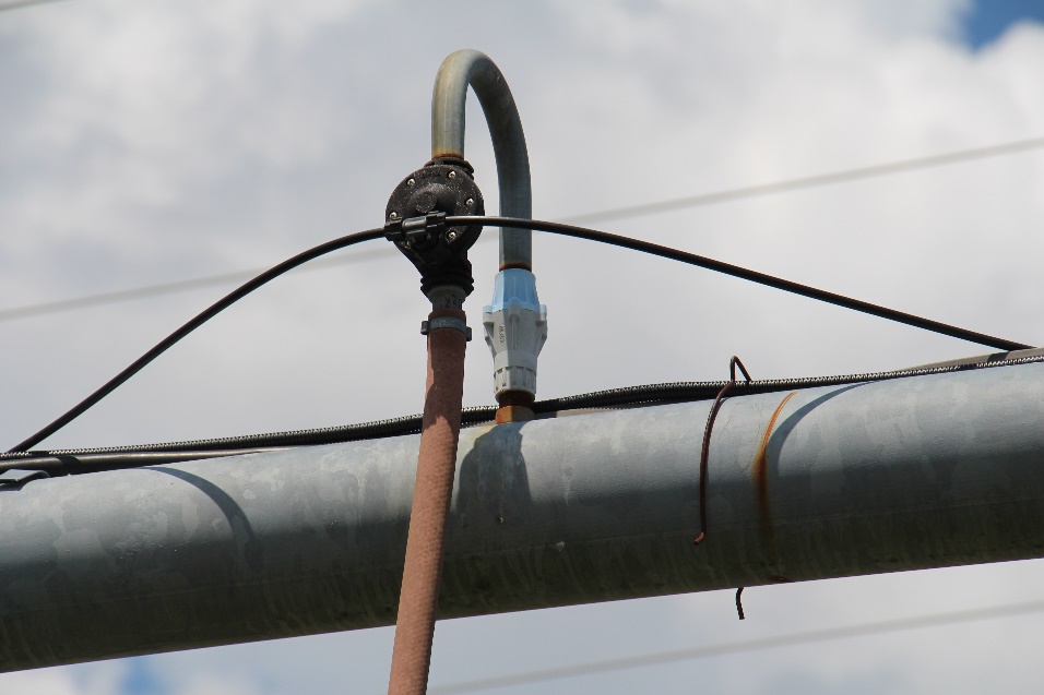
Verify proper pressure readings at the pump and the pivot point (Figure 5). Always check the pressure with the pivot parked in the same spot, with the end gun in use. Compare these readings to the pressures listed on the manufacturer’s sprinkler chart. Any case of conflicting pressures could be an indication of a problem and should be investigated further. Systems that are not operating at or near the designed pressure most likely will have uniformity issues.

Flow
With the pivot fully operational and the end gun on, check the system flow rate at your installed flow meter. Compare the readings to the design flow rate on the sprinkler chart. Just like the pressure reading, check the flow rate wherever applicable. Verify that the flow meter is working. If the meter does not appear to be working correctly, contact the Georgia Environmental Protection Division.
Sprinklers
Walk along the length of the operating pivot looking for malfunctioning sprinklers and note their locations along the system. Check for clogs, worn impact plates, missing sprinklers, etc. If possible, verify that each sprinkler matches the sprinkler head (Figures 6 and 7) specified in the sprinkler chart. Remember that 50% of the crop is irrigated by sprinklers on the last 30% of the center pivot system. Sprinklers wear out over time and need replacing, so do not assume that they are performing correctly without checking them. If the sprinklers do not seem not to be applying the correct irrigation rates, seriously consider performing a uniformity check (details to follow).


End Gun and Booster Pump
Check all parts of the end gun (Figure 8) to ensure that there are no leaks. Make sure the booster pump is working correctly, and also confirm that all moving parts and stops in the end gun are working and set correctly. Set the end gun forward and reverse angles according to the pivot design sheet. Check for any signs of wear and replace components as necessary. In most pivots the end guns cover a large percentage of the acres watered by the system, so their proper operation is very important.

Uniformity
Consider performing a “catch-can” test to evaluate water application uniformity. Instructions can be found in UGA Extension Circular 911, Evaluating and Interpreting Application Uniformity of Center Pivot Irrigation Systems. Non-uniform application may result in streaking of crop growth and/or yield. This test can also identify whether or not individual nozzles (Figure 9) are performing within specifications.

Regulators
Most current center pivots and, in particular, pivots that encounter varying terrain or have variable rate irrigation should be fitted with pressure regulators (Figure 10). Visually verify that the regulators are working properly by ensuring that each nozzle has an equivalent flow to adjacent nozzles. If a nozzle seems to be operating at a higher pressure than the neighboring nozzles, or if the regulator is leaking, further evaluate the regulator. Replace missing, leaking, or malfunctioning regulators if needed. Remember that regulators are specified by pressure and flow rate range.
Drain (Check) Valves
These valves allow air out of the pivot lines when filling with water. They act as drains once the pivot shuts off (Figure 11). During the sprinkler inspection, check all of these valves to ensure that they are functioning properly. A valve stuck in the open position will increase water loss due to excess water application. If a valve is stuck closed, it will not allow the water to drain from the pivot main line. Determine why the valve is malfunctioning, and either repair or replace it.
Leaks
This is probably the easiest problem to identify. Leaks result in pressure and water losses and should be repaired. Though they sometimes seem minor, leaks can have significant impacts on pivot pressure and therefore application uniformity.
Alignment
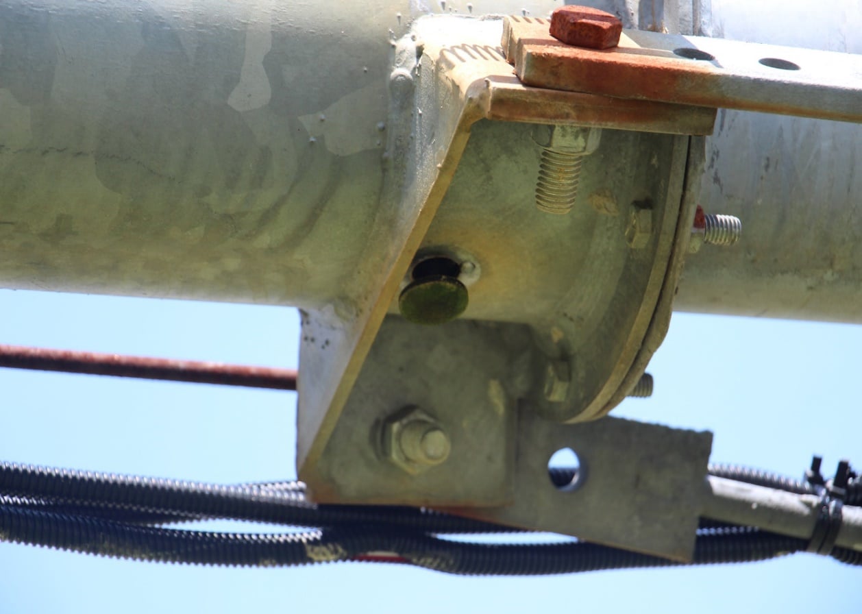
Verify that the center pivot operates in proper alignment with the towers. A misalignment issue can cause significant problems between pivot sections (Figure 12).
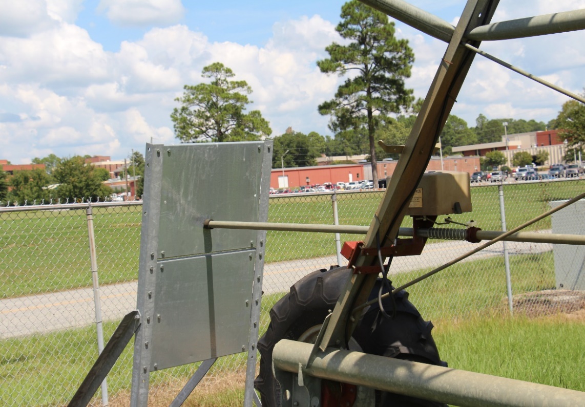
Safeties
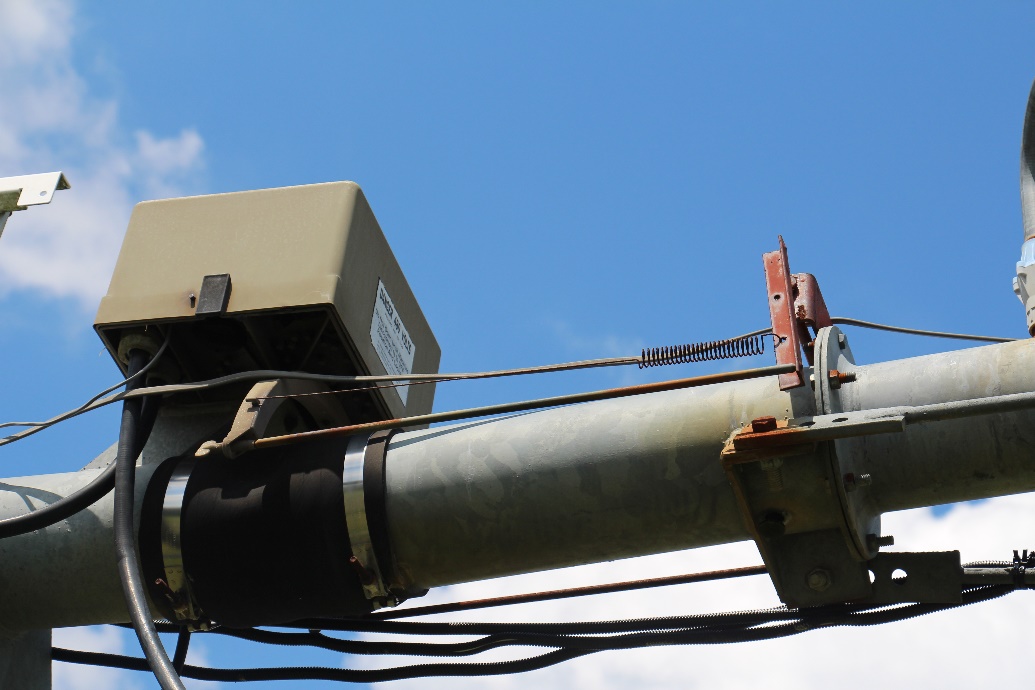
Test safety circuits to verify proper performance. It is very important that all safety and stop switches are working correctly (Figure 13). Malfunctioning safeties and stops can cause damage to the system or objects in its path.
Tires

Check for wear, cracking (Figure 14), low pressure, etc. Typically, wintertime is when tires will leak and go flat. Replace any tires that are in questionable condition to avoid having to do this mid-season. Make sure all lugs are tight.

Gearboxes / Drivelines
Remove drain plugs to allow any condensed water to drain away (Figures 15, 16, and 17). Check the oil level, and grease any fittings on the driveline. Then, repair damaged shields, and make sure that drive shafts are in good operating condition, not bent or damaged. If the oil level was noticeably low or there are signs of leakage, check with your local irrigation dealer for special gearbox oil that provides multiyear leakproof performance.


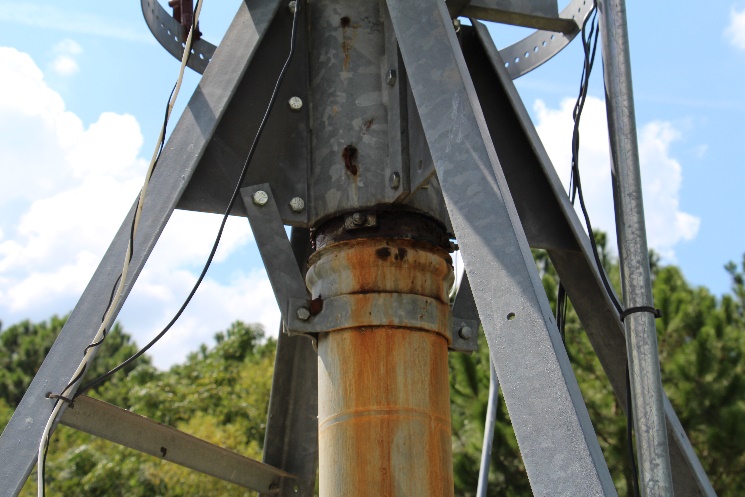
Pivot point
Inspect the anchor bolts and grease the pivot point (Figures 18 and 19).

Autostop / Autoreverse / End-Gun Coverage
Test the control panel settings for autostop, autoreverse, and end-gun coverage areas. Some pivot stops/auto reverses have been made out of wood or lightweight steel. Ensure the stops have not rotted or rusted to the point that they cannot activate the push sensor. Make sure end-gun watering angles are set properly. Avoid applying water to public roadways with the end gun, as this can become a liability issue.
Chemigation Equipment
Check the pump and safety equipment as well as the calibration of the pump. Verify that all hoses and seals are in good working order and are not cracked or leaking. Also, be mindful of the Department of Agriculture requirements for chemigation and fertigation. The system must meet the rules and guidelines of proper low-pressure drains, relief valves, and check valves in order to be in compliance with the law..
RELATED PUBLICATIONS
Harrison, K. A. (2012). Irrigation pumping plants and energy use (Publication No. B837). https://extension.uga.edu/publications/detail.html?number=B837
Harrison, K. A., & Tyson, A. W. (2012). Irrigation pumping plant performance (Publication No. C965). https://extension.uga.edu/publications/detail.html?number=C965
Porter, W., Hall, D., Mallard, J., & Perry, C. (2023). Evaluating and interpreting application uniformity of center pivot irrigation systems (Publication No. C911). University of Georgia Cooperative Extension. https://extension.uga.edu/publications/detail.html?number=C911