
Spinner-disc spreaders are commonly used for applying lime and fertilizer to agricultural fields. Uniform and accurate application of lime and fertilizer is essential. The performance failures of agricultural materials can be directly related to improper and uneven application, careless equipment operation, and the separation of blended material due to size and density differences. The uneven distribution of lime and fertilizer can reduce yields. Effects of uneven lime or fertilizer distribution are most notable in fields that are low in soil fertility, because the response to applied nutrients is greatest on these soils.
Proper setup and calibration of application equipment is important to assess its performance and attain satisfactory results. Even new and well-maintained equipment needs calibration checks regularly before and during the growing season. This is especially important when changing from one type of material or blends to another, when changing application rates, and when altering speeds or other operating conditions.
Calibration
Calibration checks for fertilizer equipment should provide information on the type of spread pattern (including the degree of uniformity obtained across the swath), the effective swath width, and the rate of application. Calibration checks should be performed to determine any necessary adjustments to maintain or improve the characteristics of the applicator.
One practical method of calibrating lime and fertilizer spreaders requires the following supplies:
- Collection pans with a gridded baffle placed in the bottom of the pan (the baffle prevents the material from bouncing out)
- Test tubes for each pan (approximately 100 ml size and labeled the same as the collection pans)
- Test tube rack and funnel
- 100- to 200-ft measuring tape
- Flags for marking pan locations
Make sure the size of the test tubes are in proportion to the rates of application being checked. All collection pans must be of identical size and shape. Pans should be shallow (2.5- to 4-in. deep) with a collecting area of 1.25 to 3 sq. ft each. The following table can be used to determine the rate of application from any size collecting pan:
| Materials collected (grams per sq. ft)* | Rate of application (lb per acre) |
|---|---|
| 1 | 96.0 |
| 5 | 480.2 |
| 15 | 960.3 |
| 20 | 1440.5 |
| 25 | 2400.8 |
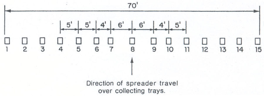
The spacing interval between pans may be changed, depending on the swath width. The spreader is adjusted for a given rate of application and operated at normal field speed in a direction perpendicular to the line of pans and straddling the center pan. Material collected in each pan is then transferred into the corresponding test tube in the rack. Use flags to mark the position of the pans along the swath so they can be placed at their original position for the next spreader pass.
The amount of material in the test tubes provides a quick, visible evaluation of the spread pattern (see Figure 2). If the spread pattern is uniform across the swath, all of the center tubes will be filled to approximately the same height and the material will be deposited uniformly on the land.
The effective swath width can be determined by locating the point on the right and left side of the swath where the tubes are filled to about one-half the height in the center tubes. The distance between these points is the effective swath width and should be used as the swath spacing (Figure 2).
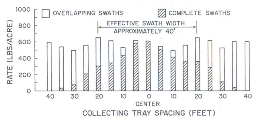
For the selected test tubes (1/2-in. diameter and 6-in. tall), the first 1/2 in. of material in each tube represents a rate of approximately 100 pounds per acre. Each 3/8 in. of material after the first 1/2 in. represents an additional 100 pounds per acre. This assumes the material has a density of 65 pounds per cubic ft, that the material in each tube is collected from an area of 1.25 sq. ft., and that test tubes with an inside diameter of 1/2 in. are used. Fertilizers vary in moisture content, particle size and density. These variations in materials will cause slight errors in the indicated rates of application. However, the method given above provides a close approximation.
Where application rates are more than 1,100 pounds per acre, larger test tubes (an inside diameter of 7/8 in. and 8- to 10-in. tall) can be used with the same collection pans. When using these test tubes, the first 1/16 in. of material in these tubes represents approximately 500 pounds per acre, and each additional 1/2-in. depth indicates about 500 pounds per acre. The larger test tubes are suggested for evaluating spread patterns for rates of application between 1,000 and 6,000 pounds per acre, such as for application of lime.
When possible, use collection pans with tapered sides as they will nest together and require minimum storage space. Removable grid baffles in the pans aid in preventing the material from bouncing out. A plastic grid material (1/2-in. by 1/2-in. by 1/2-in.) provides a satisfactory baffle. Many building suppliers stock plastic grid material (called egg crates) for recessed lights and air ducts that may be cut to size and used satisfactorily in collection pans. The pans and grid baffles are very light weight and when nested together are easy to handle.
Adjustment in Spread Pattern
Once an evaluation of a spread pattern is made, the operator should determine what, if any, adjustments can be made to improve the pattern.
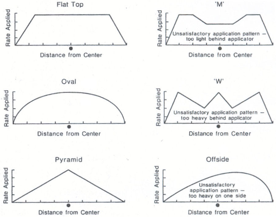
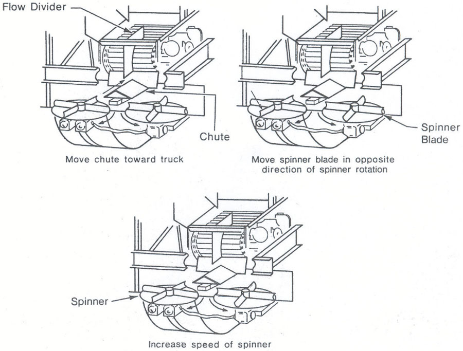
Spread patterns for a dual spinner-disc fertilizer applicator can be classified into six different types (Figure 3). The flat top, oval, and pyramid patterns are the most desirable because they allow a more uniform overlapping of the swaths. The most common undesirable patterns are the M, W, and offside (skewed or lopsided) patterns. The M pattern can be improved by making one or more of the following adjustments (see Figure 4):
- Move the delivery chute toward the applicator to change the point of delivery of the material closer to the outer edge of the spinners.
- Move spinner blades in the opposite direction of the spinner rotation.
- Increase the spinner speed. A spinner speed of 550 to 650 RPM (revolutions per minute) is recommended. Higher spinner speeds can shatter the granules, which leads to segregation and uneven distribution.
The W pattern may result from applicator conditions similar to those causing the M pattern, but it has a heavy deposit in the center of the swath in addition to concentrations on both the right and left sides. The heavy center concentration may be caused by an improperly adjusted delivery chute or leaks that permit material to fall immediately behind the applicator. Also, wet material that sticks to the conveyor belt or chain can fall in the center, causing a heavy application immediately behind the spreader. Inspect the spreader carefully to determine the reason for heavy application at the center and correct it. After appropriate spreader adjustments, the W pattern then becomes an M pattern. One or more changes should alter the M pattern to an acceptable flat top, oval or pyramid pattern.
Lopsided patterns, either right or left, may result from dual spinner-disc applicators because of uneven delivery of fertilizer material to the spinners. This is usually caused by an improperly adjusted material flow divider. Operations on steep slopes can also produce heavier flow to the downhill side if an effective flow divider is not included in the system. This problem can be overcome, to some extent, by proper overlap between swaths and application in a circular pattern.
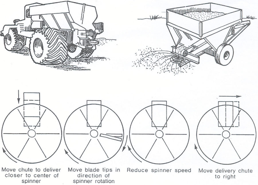
Single spinner-disc fertilizer applicators can also produce a lopsided pattern when the delivery of the material to the spinner is not positioned properly. If the right half of the pattern from a clockwise rotating spinner is heavier than the left half, any of the following adjustments will improve the pattern by delaying the release of fertilizer from the spinner (Figure 5):
- Adjust the delivery chute to deliver closer to the center of the spinner.
- Move the spinner blade tips in the direction of spinner rotation.
- Reduce spinner speed.
- Move the delivery chute to the right or clockwise on the spinner.
Similarly, heavy applications to the left side will require adjustments in the opposite direction to those listed above or as shown in Figure 5.
Troubleshooting
In addition to evaluating spread patterns, mechanical problems can also cause fertilizer application and/or distribution irregularities. Some common problems include:
- Irregular placement of slats on the conveyor chain or belt.
- Reversed hydraulic lines to hydraulic spinner motors. This reverses the direction of spinner rotation and completely disrupts the spread pattern.
- Worn and bent spinner-discs and spinner blades.
- Buildup of fertilizer and lime on spinner-discs and spinner blades.
- Lack of proper flow dividers and delivery chutes for directing material on spinners.
- Frozen adjustment mechanisms such as mechanical spinner valves or flow divider.
- Corroded and rusty hoppers and components.
Accurate Spreading Requirements
Accurate and uniform application of lime and fertilizer depends on meeting the following spreading requirements:
- Accurate metering – Make sure graduations are present on the feed gate to aid in determining application rates for various effective swath widths. Keep a notebook showing important spreader settings (e.g., gate height, spinner speed, etc.) for different materials from calibration tests in the trucks for reference and ready to use when needed.
- Proper delivery of material to the spinner or boom units – An adequate flow divider and adjustable delivery chute (Figure 4) are necessary for uniform application, especially on hillsides and in other adverse field conditions.
- Uniform distribution across swath – Spinner speed, blade pitch, and flow divider position are critical. With auger boom distributors, slide position and auger speed must be adjusted for uniform spreading at various application rates.
- Skilled and conscientious operators – Accurate spacing of swaths is essential and requires careful driving. Swath spacing should be the same as the effective swath width. A constant ground speed is important for a uniform application, especially for spreaders without a rate controller. In addition to driving, make sure that operators study the operator’s manual for their particular machine and know how to calibrate the spreader for various materials and rates of application. They should pay particular attention to cleaning, adjusting, maintaining, and repairing their spreaders properly. Auto-guidance and guidance systems such as lightbars can greatly enhance the lime and fertilizer application by allowing the operator to consistently maintain parallel adjacent passes.
In addition to following the spreading requirements listed above, operators should also regularly check spread pattern and make the necessary adjustments when changing the material or the rates of application. Remember, a heavy application of wet lime requires entirely different adjustments from a light application of high-analysis, free-flowing, blended material.
When it is practical, drive spreaders around fields in a perimeter pattern to minimize the effect of variations in spread patterns.
Granular or pelletized materials of uniform particle size and density will provide the most even and uniform application. For blended fertilizers, it is best to select materials that are approximately the same particle size, density, shape, and moisture content (this prevents segregation of materials in the spreading operation). Vertical baffles in gravity bins are effective in preventing segregation.
Remember, even with proper adjustments, it is difficult to maintain a completely uniform and accurate application rate of lime and granular fertilizer if wind speeds exceed 10 miles per hour. Therefore, it is highly recommended not to perform the spread pattern calibration, and make lime and fertilizer applications when wind speed is greater than 10 mph.
Test Kits
Calibration test kits can either be built at a considerable savings or purchased directly from commercial vendors.
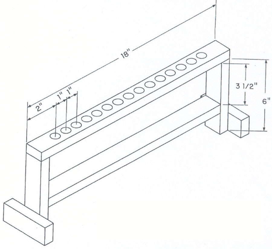
Test kits can be easy to make. Pans can be purchased and the grid baffles can be cut to fit the pans using a band saw or jigsaw. Test tubes of the proper size are available through various vendors. Figure 6 shows the test tube rack (with dimensions) for the small test tubes.
Calibration kits (including collection pans, tape measure or rope marked at pre-determined intervals, test tubes, and test tube rack) are also available for purchase from various fertilizer application equipment manufacturers or dealers at a reasonable cost.
This manuscript previously was revised by Paul E. Sumner, Extension Engineer, and Simer Virk, Extension Precision Ag Specialist.