Chemigation can save time, reduce labor requirements, and conserve energy and materials. Chemigation is beneficial, however, only to the extent that the irrigation system is adequately designed, fully functional, and properly managed.
In many situations, chemigation is as good or better than conventional application methods. Conventional application is still preferred or required, however, for some materials. Never inject any material that is not labeled and recommended for the crop and for injection through the system. Always follow label directions.
Chemigation Terminology
Chemigation is an inclusive term referring to the application of a chemical into or through an irrigation system. It includes the application of fertilizers, acids, chlorine, and pesticides.
Fertigation is specifically the application of fertilizer (plant nutrients) through an irrigation system.
Acidification is the introduction of an acid, such as phosphoric, sulfuric, or hydrochloric (muriatic) acid into an irrigation system.
Chlorination is the introduction of chlorine, such as liquid sodium hypochlorite (household bleach) or chlorine gas into an irrigation system.
The Benefits of Chemigation
- Uniform application — Chemigation helps provide uniform distribution and precision placement of fertilizers and other chemicals.
- Timely application — In most cases, materials can be applied regardless of weather or field conditions.
- Reduced application costs — In general, cost of application by chemigation is about one-third the cost of conventional application methods.
- Improved management — Timely applications of small but precise amounts of fertilizer directly to the root zone allow growers to effectively manage fertilizer programs. This conserves fertilizer, saves money, and optimizes yield and quality.
- Reduced soil compaction — Chemigation reduces tractor and equipment traffic in fields. This reduces soil compaction.
- Reduced mechanical damage to crop — Less tractor and equipment traffic in fields also means less chance of equipment potentially damaging the crop.
- Reduced exposure to chemicals — Chemigation minimizes operator handling, mixing and dispensing of potentially hazardous materials.
- Reduced environmental contamination — When used with the recommended safety devices, properly designed and accurately calibrated chemigation systems help preserve quality of the environment.
- Rescue treatment — Chemigation can be used as a rescue treatment when dealing with low fertility in plants or if the producer gets behind on mechanically fertilizing the crop.
The Disadvantages of Chemigation
- Chemical/fertilizer reaction with equipment — Some chemicals and fertilizer may react with irrigation system components and could be corrosive to equipment if the system is not properly flushed.
- Equipment cost — Some chemigation rigs can be rather costly. Additional capital outlay is required for equipment. Components such as injectors, tanks, and safety devices will be required.
- Intensive management — Chemigation requires a change in management techniques. Operator training is required to ensure that the operator is careful, attentive, and understands backflow prevention equipment, injector calibration, and the operation of the irrigation system being used.
- Chemical properties — Some chemicals cannot be used for chemigation due to their chemical properties. These particular chemicals could potentially clog the nozzles or emitters on your irrigation system. Drift hazards may also be an issue with certain chemicals.
- Chemical labeling — Not all chemicals are labeled for use in chemigation.
- Increased application timing — Chemigation increases application time compared to aerial or ground spraying, so climatic factors can interfere with or delay application.
- Environmental contamination is possible — If proper safety equipment is not used, water sources can be contaminated. Runoff from chemically laden water to other areas is possible.
General Principles of Chemigation
| Irrigation method | Relative uniformity | Suitability for chemigation/fertigation |
|---|---|---|
| Center pivot | Good to excellent | Yes |
| Solid set gun | Poor | No |
| Traveling gun | Poor | No |
| Drip/trickle | Excellent | Yes |
Safety Considerations
The irrigation pumping plant and the chemical injection pump should be interlocked. Simply stated, if the irrigation pumping plant were to stop, the chemical injection pump should also stop. This will prevent chemicals from the supply tank from filling irrigation lines if the irrigation pump should stop. With internal combustion engines, the chemical injection pump can be belted to the drive shaft or an accessory engine pulley. Injection pumps driven by electric motors require a separate one-third or one-half horsepower electric motor for the chemical injection pump. Controls for the motors should be electrically interlocked to stop the injection pump motor whenever the irrigation pump stops. This is shown in Figure 1 for electric motors.
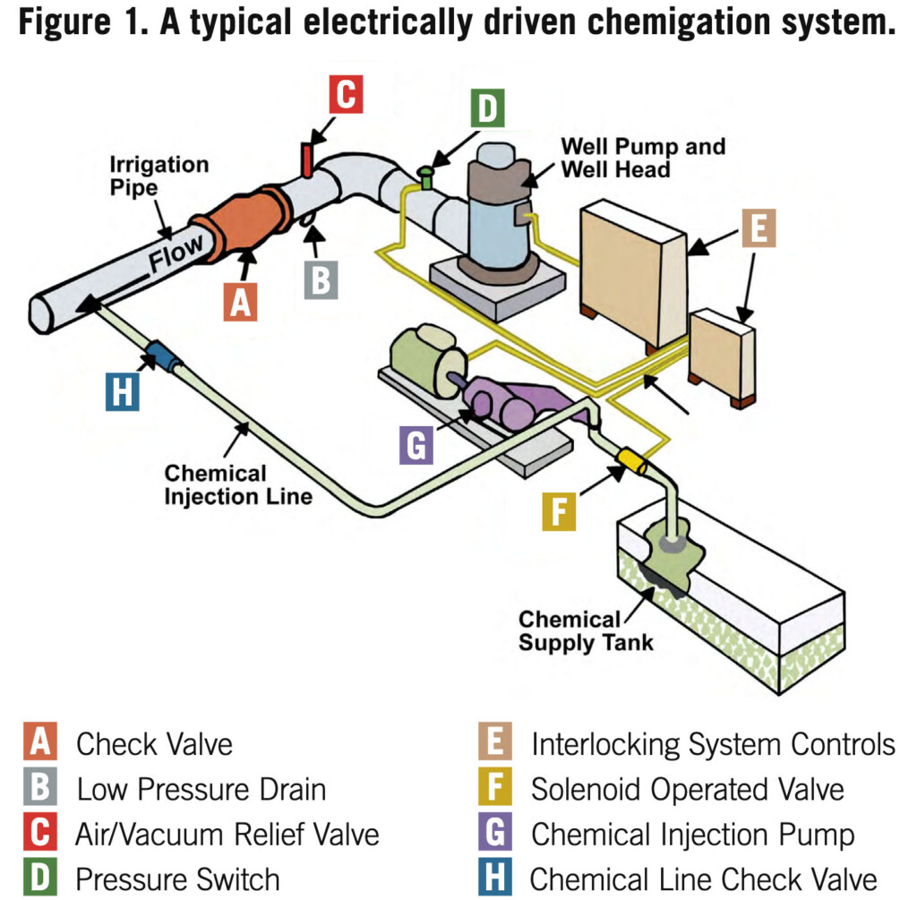
Check and vacuum relief valves (anti-siphon devices) are necessary safety devices. They prevent water or mixtures of water and chemicals from draining or siphoning back into the water source. Both valves must be located between the irrigation pump discharge and the point where chemicals are injected into the irrigation pipeline (Figure 1).
A check valve should be installed in the chemical injection line to prevent the backflow of water from the irrigation system into the chemical supply tank. If the injection pump stops and there is no check valve, irrigation water can flow through the injection line into the chemical supply tank. Subsequently, the tank may overflow and cause a chemical spill around the water source. Chemicals from such spills can contaminate ground and surface water. An additional safety item is a small, normally closed solenoid valve to be electrically interlocked with the engine or motor that drives the injection pump. This solenoid valve provides a positive shutoff in the chemical injection line, which stops chemical or water flow in either direction if the injector pump stops.
For automated control, a pressure switch should be electrically interlocked with the safety panel on the irrigation system. This switch will automatically shut down the irrigation system and the injection pump if pressure is lost in the injection discharge line. Usually, loss of pressure in injection lines occurs when the chemical tank is pumped dry or chemical lines burst.
The American Society of Agricultural & Biological Engineers (ASABE) standard EP 409.1 can be used as a general guideline for agricultural antisiphon devices.
Injection Methods
Two basic types of injection methods — the Venturi (Figure 2) and the metering pump (Figure 3) — are commonly used for injecting fertilizer and other chemicals into drip-irrigation systems. Field set-ups for both types should have an adjustable injection rate. Any components that will be in contact with fertilizer, chlorine or acid should be resistant to corrosion.


Determining Injection Rate (What size injector do I need?)
Before calibrating the injection pump, determine the desired injection rate. Use the following steps as a guide.
- Determine the area (acres) to be chemigated.
- Determine the volume of chemical solution (gallons) to be applied per acre.
- Determine the total number of gallons needed to treat the area (step 1 x step 2).
- Determine how long (hours) it will take the system to cover the area in step 1 if using a center pivot irrigation system, OR determine how long (hours) the system will be run during this chemigation event if using drip or solid set irrigation system.
- Calculate the desired injection rate in gal/hr (step 3 divided by step 4).
- Use the following equations to convert gallons per hour (gal/hr) to milliliters per minute (ml/min) or ounces per minute (oz/min).
- Equation 1: 63.09 x gal/hr = ml/min
- Equation 2: 2.13 x gal/hr = oz/min
Calibrating the Injection Pump
Chemigation should never be attempted without accurate calibration. Manufacturers’ suggested settings are helpful guides. However, to ensure that recommended amounts are being applied at the desired concentrations, calibrate the injection pump on-site.
The objective of calibrating the injection pump is to adjust the pump injection rate to the actual injection rate. The pump injection rate is determined by measuring the volume of solution pumped through the injection pump (injected volume) during a specific duration of time (usually 60 to 120 seconds). The injected volume can be determined by any of the following methods:
Method 1 — Using a graduated cylinder, measure a selected volume of the solution to be injected. The selected volume should be of sufficient quantity to allow injection for several minutes. Place this known volume into a container connected to the intake line of the injection pump. With the system operating and fully charged, activate the injection pump and determine the number of seconds required for this known volume to be injected.
Method 2 — This method is similar to the above method. The primary difference is only a portion of the measured chemical solution is injected. Using a graduated cylinder, measure a selected volume of the solution to be injected. This selected volume should be of sufficient quantity to allow injection for several minutes. Place this known volume into a container connected to the intake line of the injection pump. With the system operating and fully charged, activate the injection pump for a specific duration of time. This injection period should be for several minutes. However, it should be short enough so that only a portion of the solution is injected. At the completion of the injection period, measure the volume of solution left in the container. The volume of injected solution is determined by subtracting the amount remaining after injection from the original volume.
Method 3 — In this method, the solution pumped through the injection pump during a given period of time is collected and measured. With the system operating and fully charged, activate the injection pump for a specific time (two to five minutes). Divert the output line from the injection pump into a container. A pressure regulating device should be installed on the output line to simulate system back-pressure. Measure the output with a graduated cylinder to determine the volume of chemical injected. Since operating pressures and flow characteristics of irrigation systems may influence injection rates, for methods 1 and 2, it is necessary to perform calibration procedures with the irrigation system operating and fully charged. Before beginning calibration, make sure the system is primed, that it is operating at the same pressure it will be during injection, and that suction and discharge lines do not contain air bubbles. Also, during calibration, keep the point of injection at the same height that it will be during actual chemigation. Once the pump’s injection rate has been determined, this rate can be adjusted until the desired injection rate is achieved.
Additional Protection Measures
The agency responsible for the enforcement and inspection of chemigation safety guidelines in Georgia is the Georgia Department of Agriculture. Current rules and regulations can be found at www.agr.georgia.gov/agricultural-pest-control. Midway down the page is the Laws and Regulations section, where you can find links to the Georgia Anti-Syphon Device Act and the Agriculture Rule about prevention of ground and surface water contamination; the latter link includes a detailed drawing of a compliant setup.
In addition to the safety equipment and measures previously described, several other devices and management measures can improve chemigation operation and safety to the environment.
- Hoses, clamps, and fittings: All components in contact with the chemical mixtures should be constructed of materials that are chemically resistant and resistant to sunlight degradation. The pressure rating of all components should be adequate to withstand all operating pressures. Protect hoses and fittings from mechanical damage.
- Injection line strainer: Install a strainer on the chemical suction line/hose to remove foreign materials that could plug or damage the injection meter/pump or chemical injection line check valve.
- Injection port location: When possible, locate the port for chemical injection higher than the chemical supply tank but lower than the lowest sprinkler outlet to prevent siphoning from the tank. The injection port must be located downstream from the main pipeline check valve.
- Injection line flow sensor: An injection line flow sensor installed just upstream from the chemical injection line check valve and interlocked with the injection device can be used to shut down the injection system if flow in the injection line ceases. This safety measure would prevent continuous operation after a line/hose ruptures or disconnects, injection device loses prime or fails, supply tank is emptied, or injection port becomes plugged. The flow sensor could also be interlocked with the irrigation system to shut down the whole system if injection line flow stops.
- Two-way interlock: A two-way interlock between the irrigation system and the injection system can stop either system if the other system also stops. This interlock will eliminate untreated areas in the field by stopping the irrigation pump and sprinkler system if the injection system stops or malfunctions. The interlock can be done electrically or with the use of a flow sensor on the discharge side of the chemical injection device. When there is no flow in the injection line, the irrigation system and pumping plants will shut down.
- Low pressure drain: There should be an automatic low pressure drain should be placed on the bottom of the irrigation pipeline. In the unfortunate event of the mainline check valve slowly leaking, the solution drains away from (rather than into) the well. The drain should discharge at least 20 feet away from the well, and the flow should also be directed away from the well.
- Solenoid valve: For added safety, install a normally closed solenoid valve on the suction side of the injection device to provide a positive shut-down on the injection line when not in use. The solenoid valve must be interlocked with the injection device power supply to open or close properly.
- Bleed valve: A bleed valve, located upstream and next to the injection line check valve, can be used to relieve locked-in pressure in the chemical injection line any time the line is to be disconnected. This will prevent the operator from being sprayed with the chemical in the line during line removal.
- Calibration equipment: A calibration tube or in-line flow meter installed on a chemigation system can provide an easy way to measure the rate of flow of the chemical being injected into the irrigation system. A calibration tube is typically a clear tube with markings in milliliters or fluid ounces and used with a stop watch to measure the flow rate. Place the tube on the suction side of the injection device with the necessary valves and fittings so the injection rate can be checked during a chemigation. An in-line flow meter can be installed in either the suction or discharge side of the injection device. Its markings are typically expressed in flow units of volume per time.
- Injection meter/pump: Locate the injection meter or pump within the chemical supply tank containment unit when available and possible.
- Portable chemigation system and chemical supply tank: Install the chemigation injection meter/pump and chemical supply tank onto a portable trailer or truck. Construct a secondary containment unit of appropriate size on the bed of the trailer or truck.
- Chemigation system location: When developing a new irrigation system, locate the irrigation well at least 150 feet from the chemigation system, chemical supply tank, injection port, power interlock controls, etc.
Management Practices
Review the operation of the irrigation system: Periodically observe the irrigation system’s water distribution pattern and conduct a water distribution test of the spray pattern. Remember that the uniformity of the chemical distribution will be no better than the distribution of the water. It is highly recommended to have a “catch-can” test performed on your center pivot prior to the growing season if you will be chemigating to make sure your pivot is applying water uniformly. UGA Extension can offer assistance on pivot uniformity tests through a free service known as the Mobile Irrigation Lab. Contact your local county extension agent if you need further assistance. Make sure your center pivot’s end gun shutoff is properly functioning to prevent spray from being applied into public roadways or other non-cropped areas. If wind speeds are greater than 10 miles per hour, shut the irrigation system down. Wind will carry chemical or fertilizer drift off target. Manage the irrigation system to prevent runoff or deep percolation of the water-chemical mixture.
Before starting chemigation, the irrigation system should be pressurized and fully operating. The travel time from the injector location to the end sprinkler on a center pivot must be determined to ensure that all of the field is treated and receives the same amount of chemical or fertilizer. The travel time to reach the furthest sprinkler may be 15 minutes or may be even longer if the injector is not at the pivot point. If the travel time is not accounted for, there will be portions of the field that may not receive any treatment.
Do not chemigate in areas containing wetlands and other surface water bodies. Do not apply any pesticide that is not labeled for use in an irrigation system. Such applications are illegal and may adversely affect wildlife, non-target plants and water quality.
- Inspect safety and antipollution equipment before each use: Inspect all components of the chemigation and irrigation system before each use. Repair or replace any components not working at the time of inspection before chemigating. Routine inspections should minimize the potential for failure of any component during chemigation. Keep a record of inspection dates for documentation.
- Filling supply tank/mixing agricultural chemicals: Direct suppliers to closely monitor the delivery of products to a supply tank. Make sure they first check the condition of the supply tank and plumbing before filling. Fill the supply tank to no more than 95 percent of capacity. Monitor the inventory of product contained in the supply tank between chemigations in order to determine if the supply tank is leaking.
- Keep chemigation site uncontaminated: To facilitate safe monitoring of the chemigation operation, do not allow the irrigation system to spray water and chemical into the chemigation equipment area. This may mean plugging a couple of nozzles on the irrigation system near the chemigation site.
- Calibration: Accurate calibration of a chemical injection device is essential for proper application. Periodically recheck the calibration setting of the injection device. Follow calibration procedures described by the chemical label or chemigation equipment manufacture. Minor differences in injection rate over an extended period can cause too high or low a chemical application. This may produce unsatisfactory results or cause potential pollution or crop damage when high applications are made.
- Agitation: If agitation is required, some form of mechanical agitation will need to be used.
- Runoff management: The irrigation system should be managed to prevent runoff of the water-chemical mixture. Precautions should be taken to prevent the runoff from leaving the field where a chemical is being applied if runoff were to occur within the field. Reduction of the application depth applied by the center pivot can reduce the potential for runoff to occur.
- Empty chemigation supply tank: Leftover pesticide mixtures should be immediately applied to another crop or site listed on the label or removed from the supply tank and stored in an appropriate place and in a marked container for later use. Rinse out the empty tank and apply the rinsing water to the irrigated crop or another labeled site. For tanks containing leftover N solution that you’re not planning to use in the next week or two, remove the N from the supply tank or relocate the tank away from the water source requirements.
- Flush injection equipment: Flush the chemigation injection device, hoses and check valve with clean water after each use. Flush cleaning water into the irrigation system while it is operating so the cleaning water will be applied to the field. Clean strainer after each chemigation.
- Flush irrigation system: After a chemigation event is completed and the chemigation system is cleaned, operate the irrigation pump as long as necessary to flush the irrigation system of chemical. This may take 10 to 15 minutes for most systems.
- Report accidental spills: If an accident occurs (regardless of size), avoid personal contamination, take action to keep the potential spill to a minimum, and report the incident to the proper authorities. In Georgia, the toll free number for technical assistance for chemical fires, spills, and medical emergency is 800-424-8802.
- READ AND FOLLOW ALL LABEL DIRECTIONS. Current pesticide information recommendations can be found in the Georgia Pest Management Handbook available from your local county Extension agent.
Center Pivot Calibration Worksheet
Determine the acres that the pivot covers and the time to make a full circle. Use this worksheet to find the acres covered and hours to make a full circle at the 100% setting.
A: Distance from pivot point to last wheel track feet
B: Time (in seconds) it takes the last tower to go 50 feet @ 100% seconds. Convert minutes to seconds = minutes x 60 = seconds
C: Wetted length (in feet) from pivot point to end of end gun range feet. To get this, measure from the pivot point to the end gun and add range of the end gun
D: Circumference of last wheel tract = A x 2 x 3.1416 = feet
E: Minutes (decimal) to run 50 feet = B/60 = minutes per 50 feet
F: Feet per minute= 50/E = feet/minute
G: Wetted acres (with end gun on 100% of circle)= C x C x 3.1416= square feet. Divided by 43560 = ______ acres
H: Minutes to make full circle = D/F minutes
I: Hours to make full circle H/60= hours
J: Acres per hour G/I = acres per hour